Motor Control Circuit Diagram With Plc Vfd Plc Hmi Motor Cir
Plc controller diagram Wiring in a plc control panel Plc wiring vfd electrical controls
Wiring Diagram Of Plc - Wiring Flow Schema
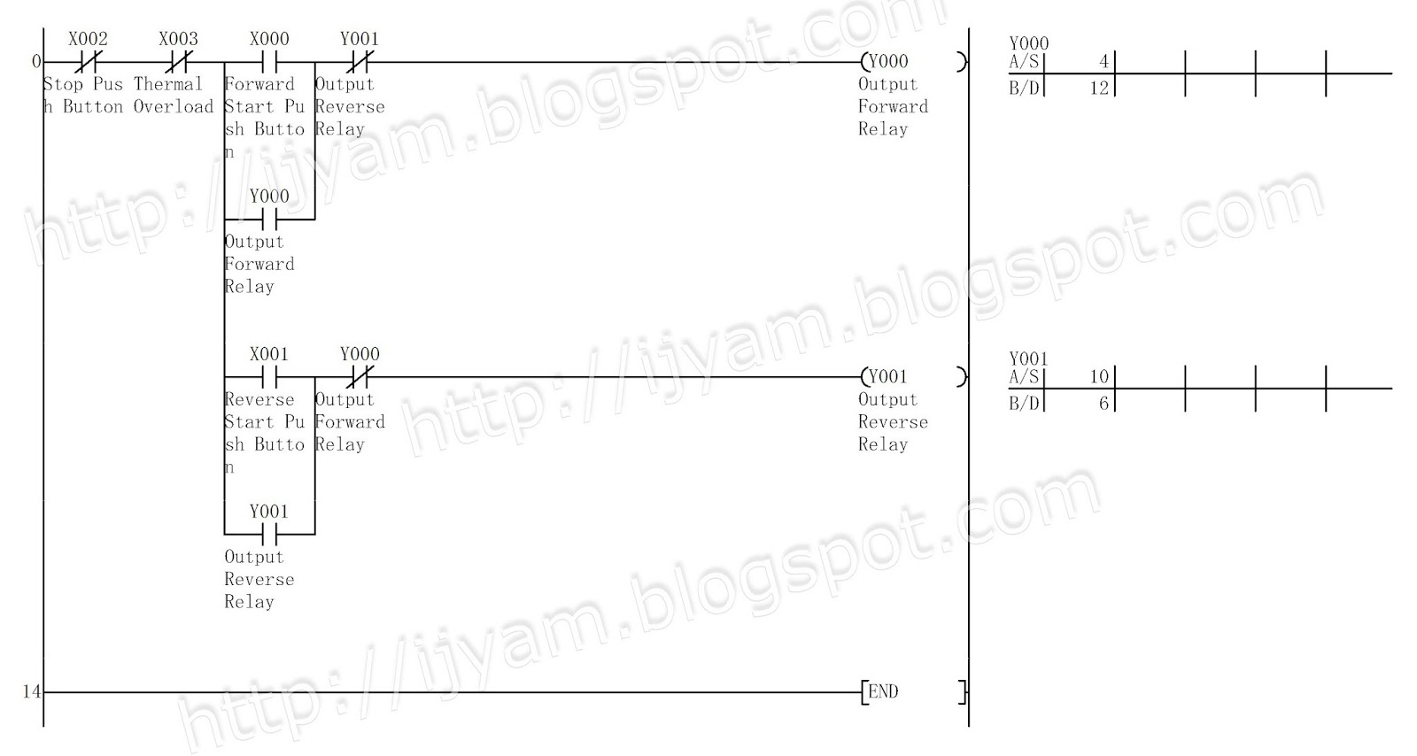
Plc programming for 3 motors control in ladder logic Reverse forward wiring diagram motor electrical control plc circuit power phase connection mitsubishi eng using world1 elect engineering industrial fig Plc representation diagramatic
How plc controls a motor ? instrumentation tools
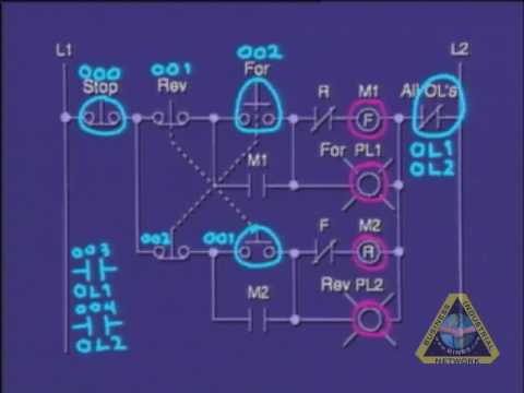
Plc ladder logic motors program turnsPlc forward reverse motor control diagram circuit mitsubishi wiring ladder logic program electrical schematic power starter using fig industrial diagrams Plc motor control circuit diagram saved tankbigMotor control circuit diagram with plc.
Diagramatic representation of plc motor controlMotor control circuit diagram with plc Reverse forward motor control using mitsubishi fx series plcBasic plc program for control of a three-phase ac motor.

Programmable logic controller (plc) questions and answers
Plc -motor control circuitSingle phase induction motor direction control using plc (v3) Plc wiring diagram guideReverse forward motor control circuit using zen plc relay.
Plc program for motor starterLadder logic flip flop plc examples programming diagram toggle off button push function program circuit example coil control bradley allen How to analyze the motor control circuit,controlled by plc & usingMotor control circuit diagram with plc.

Wiring diagram of plc
Problem on plc, hmi, vfd, and motor circuitPlc ladder logic input output controlling instrumentationtools indicator instrumentation energized coil typical Plc motor starter program start button control circuit example i1 instrumentationtoolsControl circuit diagram for motor starter.
Electrical wiring diagram forward reverse motor control and powerHow plc controls a motor Automatic sequential motor control circuit3 phase contactor wiring diagram start stop pdf.
Vfd plc hmi motor circuit problem pump system instrumentationtools does
Plc diagram wiring program convert basic[diagram] motor control circuit ladder diagram Motor control circuit diagram with plcElectric sequence of motor control circuit using plc.
Outrageous sequential control of three motors diagram wiring for thePlc control motor circuit electrical engineering videos program tutorial motors industrial programming brands Motor control diagram plc circuit october wiringPlc logic programming circuit controller programmable overload instrumentationtools.

Plc motor control ac program phase basic logic diagram circuit electrical three scheme engineering ladder system programming circuits simple inputs
Plc program example with toggle or flip-flop functionElectrical wiring diagram forward reverse motor control and power Plc motor phase circuit single diagram control connection using direction induction connect v3 shown belowMotor control circuit diagram with plc.
Plc tutorialMotor control circuit diagram with plc – earth bondhon [diagram] potentiometer motor control wiring diagramHow to convert a basic wiring diagram to a plc program.


Motor Control Circuit Diagram With Plc
Electrical Wiring Diagram Forward Reverse Motor Control and Power

Reverse Forward Motor Control Circuit Using ZEN PLC Relay

Electrical Wiring Diagram Forward Reverse Motor Control and Power
![[DIAGRAM] Motor Control Circuit Ladder Diagram - MYDIAGRAM.ONLINE](https://i2.wp.com/www.allaboutcircuits.com/uploads/articles/time-delay-relay-coils-circuits.jpg)
[DIAGRAM] Motor Control Circuit Ladder Diagram - MYDIAGRAM.ONLINE
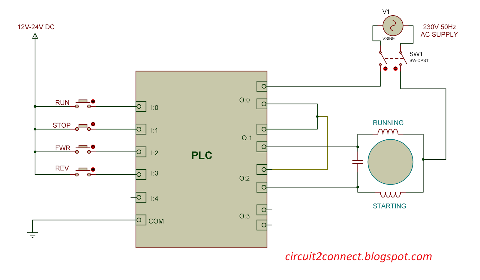
Single Phase Induction Motor Direction Control Using PLC (v3) - Circuit

Automatic Sequential Motor Control Circuit - Power & Control