N Bit Full Adder Using Half Adder Circuit Diagram Adder Inpu
Building a full adder using half adders📋 📋 Jelaskan perbedaan half adder full adder dan paralel adder pada Adder adders vhdl logic implementation explanation
5-BIT PARALLEL ADDER ~ Creative Engineering Projects
What is half adder and full adder circuit Circuit diagram full adder using cmos Full adder
13+ full adder block diagram
Full adder logic gate circuit diagram template logic logic gatesDesign full adder circuit using decoder and multiplexer Half adder circuit diagramHalf adder and full adder with equation in digital electronics.
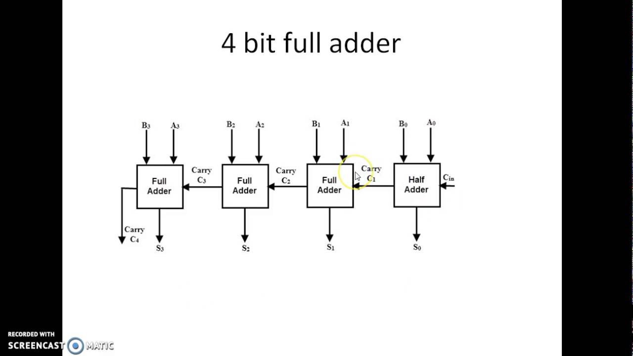
Adder circuit ripple[diagram] logic diagram of full adder Draw and explain 4-bit binary adder circuit5-bit parallel adder ~ creative engineering projects.

Adder bit using full circuit adders four half circuits watson box just single into implementation outputs latech edu
Adder full half circuit carry ripple bit schematic diagram gate truth table delay electronics doubt without xor representation shown singleFull adder using half adder circuit diagram Design a full adder and subtractor circuitVhdl tutorial – 10: designing half and full-adder circuits.
What is half adder and full adder circuit?Vhdl code for full adder using structural method Digital logic design: full adder circuitAdder inputs.
![[DIAGRAM] Logic Diagram Of Full Adder - MYDIAGRAM.ONLINE](https://i2.wp.com/qph.fs.quoracdn.net/main-qimg-c11f15f42c2ae5acea8497a6ea6e2561)
Full adder circuit diagram using half adder
Implementation of full-adder using two half adder and or gateAdder gate adders vhdl structural logic implementation bench test explanation Full adder equationWhat is half adder and full adder circuit?.
8 bit parallel adder circuit diagramDraw and explain 4-bit binary adder circuit [diagram] bcd adder circuit diagramHow to design half adder and full adder circuits?.

What is half adder logic circuit?
4-bit adder subtractorFull adder circuit – how it works Adder input outputs alongDifference between half adder and full adder.
Adder circuit full logic using digital boolean diagram implement implementation functionAdder vhdl circuits designing ckt Half adder circuit and its construction4-bit adder and subtractor circuit explained.

Full adder circuit diagram using half adder
.
.
![[DIAGRAM] Bcd Adder Circuit Diagram - MYDIAGRAM.ONLINE](https://i2.wp.com/www.electronicsengineering.nbcafe.in/wp-content/uploads/2014/09/full-adder.png)

What is half adder logic circuit? - Rankiing Wiki : Facts, Films

4-bit Adder Subtractor - VLSI Verify

5-BIT PARALLEL ADDER ~ Creative Engineering Projects
8 Bit Parallel Adder Circuit Diagram

Full Adder Circuit – How it Works

What Is Half Adder And Full Adder Circuit - BEST GAMES WALKTHROUGH

Half Adder Circuit Diagram